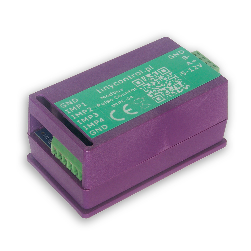
The tMPC-04 is a 4-input pulse counter with a Modbus RTU interface designed for use with meters that provide pulse outputs.
The meter provides measurement parameters via Modbus registers: number of pulses, calculated energy values and estimated power.
The device can be used with electricity meters, but it can also measure other quantities such as water or gas consumption. Conversion to these units is based on user-defined coefficients (e.g. pulses per kWh), with the default value set to 1000 pulses per unit.
Out of the box, the tMPC-04 is pre-configured with:
Modbus Slave ID: 1
Pulse Conversion Factor: 1000 pulses per unit (e.g., imp/kWh) for all 4 inputs
If these settings match your energy meters, the device is ready for immediate use. Otherwise, for setups with multiple pulse counters or different pulse conversion factors, refer to the Advanced Configuration section.
Newer hardware revisions of the tMPC-04 include a function button that allows quick Modbus address configuration.
If you need to change the Modbus address, you can do so using the built-in function button and the LED located on the PCB. The button is placed near the edge of the board opposite the side with the USB port and the Modbus and power supply connectors.
To read the current address:
Click the button once.
The LED will blink to indicate the address.
(For example, 2 blinks = address 2.)
To set a new address:
Press and hold the button.
After 2 seconds, the LED will blink once.
Continue holding — the LED will blink once per second up to 5 times.
Release the button after the number of blinks that corresponds to your desired address.
(For example, for address 3, release after the third blink.)
⚠️ If you hold the button for more than 7 seconds, the process is canceled and no changes are made.
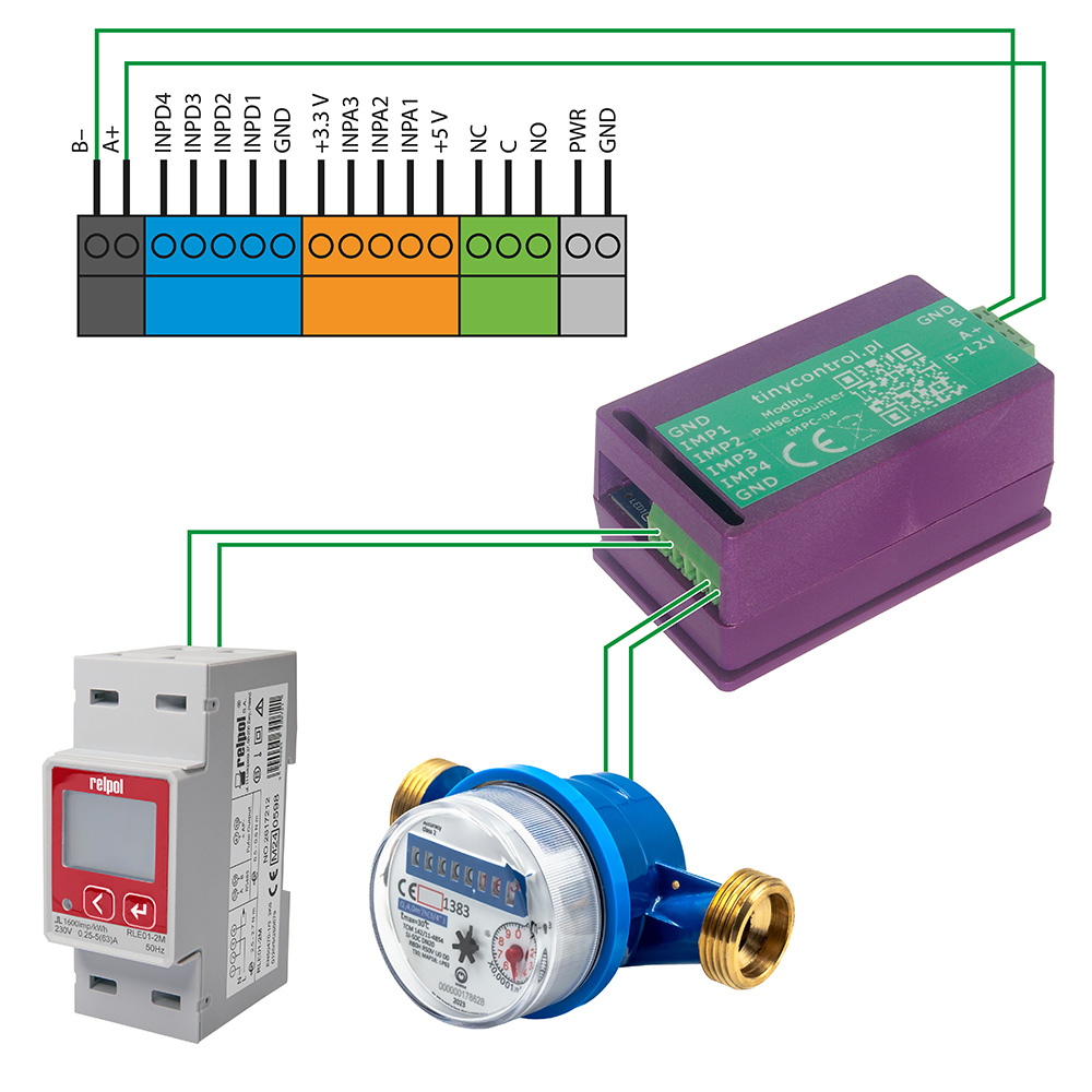
The tMPC-04 integrates seamlessly with LK4 and LK3.5+ devices. It can be powered directly from the LK controller using its 5 V and GND outputs. Then, connect it—either alone or together with other Modbus devices—to the LK’s Modbus A+ and B− terminals to establish communication.
Once connected, configure a custom Modbus module on the LK using the ready-to-use configuration preset available in the Downloads section. You can easily modify this preset to read only the parameters you need, such as selected pulse counters, energy or power values.
To update the firmware, the device must be placed into bootloader mode. In this mode, the device appears as a mass storage device named RPI-RP2 when connected to a PC. Simply copy the new firmware file to that storage. After the upload, the device will automatically restart and resume normal operation with the new firmware.
You can enable bootloader mode in one of two ways:
Via USB Console
Connect the device to a PC and open the serial console (see instructions in Advanced Configuration).
Then, send the command bootloader.
The connection will be interrupted, and the device will restart in bootloader mode.
Via JP2 jumper pad (hardware method)
Open the device casing to access the JP2 jumper pad — two adjacent contact fields on the PCB.
Temporarily short the two pads (for example using tweezers or another metal tool) before connecting the device to the PC via USB.
Keep the pads shorted briefly as the device powers on. Once it enters bootloader mode, remove the short.
On older hardware revisions, a FLASH / SW button located on the PCB is used instead.
Press and hold the button before connecting the device to the PC via USB, then release it once the device enters bootloader mode.
Firmware files are available in the Downloads section.
To modify the settings, you will need to connect the tMPC-04 to a computer via USB. The device can be powered through USB, so no additional power connections are necessary.
To establish a connection with the board, you’ll need an application that can handle serial communication. Popular choices include:
PuTTy
TeraTerm
PySerial (Python library), which includes useful tools like pyserial-miniterm (for managing connections) and pyserial-ports (for listing available COM ports).
List Available Ports
Run pyserial-ports to list the available COM ports before connecting the device. The output might look like:
COM1
COM3
COM15
COM16
COM17
Connect the Device
Plug in the tMPC-04 and run the command again. The new COM port (e.g., COM11) will represent the connected device.
Connect to tMPC-04
Use the following connection parameters:
Baud rate: 115200
Byte size: 8 bits
Parity: None
Stop bits: 1
Example command:
pyserial-miniterm COM11 115200
Send Commands
Once connected, you can issue commands to the device. Each command must be followed by the Enter key. A useful command is ? or help, which provides a list of all available commands (described below).
Set the Modbus address. Parameters: X - address to set, number <1, 255>.
debounce_time? | d?
Get debounce time for pulse counters (in ms).
debounce_time=X | d=X
Set the debounce time for pulse counters. Defines the minimum pulse length, shorter ones will be ignored and not counted. Parameters: X - value in ms, number <0, 65_535>, for 0 the function is disabled.
power_estimation? | pe?
Get power estimation flag for pulse counters (0 - OFF, 1 - ON).
power_estimation=X | pe=X
Set power estimation flag for pulse counters. Defines whether the power estimation is enabled. It can be disabled if not needed or to improve the measurement range of pulse frequency from ~2 kHz to ~4 kHz (the limitation due to the pulse duration and shape remains). Parameters: X - value 0 - OFF / 1 - ON, number <0, 1>.
auto_save? | as?
Get the value of the auto-save function. This is the interval in seconds at which the counters are saved.
auto_save=X | as=X
Set the value of the auto-save function. Parameters: X - value in seconds, number <0, 65_535>, for 0 the function is disabled.
counter_cfX? | ccfX?
Get conversion factor for pulse counter. Parameters: X - counter number <1, 4>.
counter_cfX=Y | ccfX=Y
Set the conversion factor for the pulse counter: the number of pulses per unit, e.g. imp/kWh. Parameters: X - counter number <1, 4>; Y - number of pulses, number <1, 65_535>.
counterX? | cX?
Get the value of the pulse counter, i.e. the number of pulses it counted. Parameters: X - counter number <1, 4>.
counterX=Y | cX=Y
Set the pulse counter value. Parameters: X - counter number <1, 4>; Y - number of pulses, number <0, 1_073_741_823>.
read_status | rs
Read the saved status of the counters.
save_config | sc
Save configuration to Flash memory. It should be called after changing the Modbus address, counters’ conversion factors, debounce time, and auto-save function to keep them after a restart.
save_status | ss
Save the status of the pulse counters to Flash memory. It should be called after changing the value of the pulse counters (the number of pulses) to keep them after a restart.
Reboot the device into bootloader mode to update the firmware. When connected to a computer, it will appear as a storage device named RPI-RP2, to which you should copy the firmware file with the extension uf2. Then the device will reboot into normal operation mode.
restart
Restart the device.
verbose=X | v=X
Turn on or off verbose mode, which displays more messages.
help | ?
Display this help message with a list of available commands.
Some commands are useful only in specific situations.
Modbus addressing
When using multiple tMPC-04 devices on one Modbus bus or together with another device that has the same address, it is recommended to change the address using the command address=X so that each device has a unique one.
Debounce time
If the device counts excess pulses, the command debounce_time=X can be used to ignore pulses shorter than the specified duration.
Automatic saving
If it is necessary to preserve the counter values in case of a power failure, the command auto_save=X should be used. This causes the counter state to be periodically saved to permanent memory.
Be mindful of flash memory wear, as it has a limited number of write cycles (rated for about 100k). Therefore, when using this feature, the interval should be chosen as a reasonable compromise. For example, a value of 300 seconds should allow for about one year of operation, and 1800 seconds for more than 5.5 years. The devices use a wear-leveling file system, which significantly increases the expected number of writes (our test device has already performed over 440k writes without errors).
Saving changes
After changing settings using the commands address=X, debounce_time=X, power_estimation=X, auto_save=X, or counter_cfX=Y, you must use save_config to store the configuration in permanent memory. Otherwise, the changes will be lost after a power loss or device restart.
The accuracy of pulse measurement depends on the frequency, pulse duration, and rise/fall times. In normal operation with power estimation, the pulse duration should be no shorter than 0.34 ms. In high-speed mode (without power estimation), the pulse duration can be as short as 0.19 ms.
For most applications, measurement errors should not exceed 0.1%. In our tests, if it was inaccurate it was 1 or 2 pulses too many or too few.
Below is the list of Modbus registers available in the device.
The content corresponds to the output of the read_definitions command and includes register names, addresses, types, and divisors.