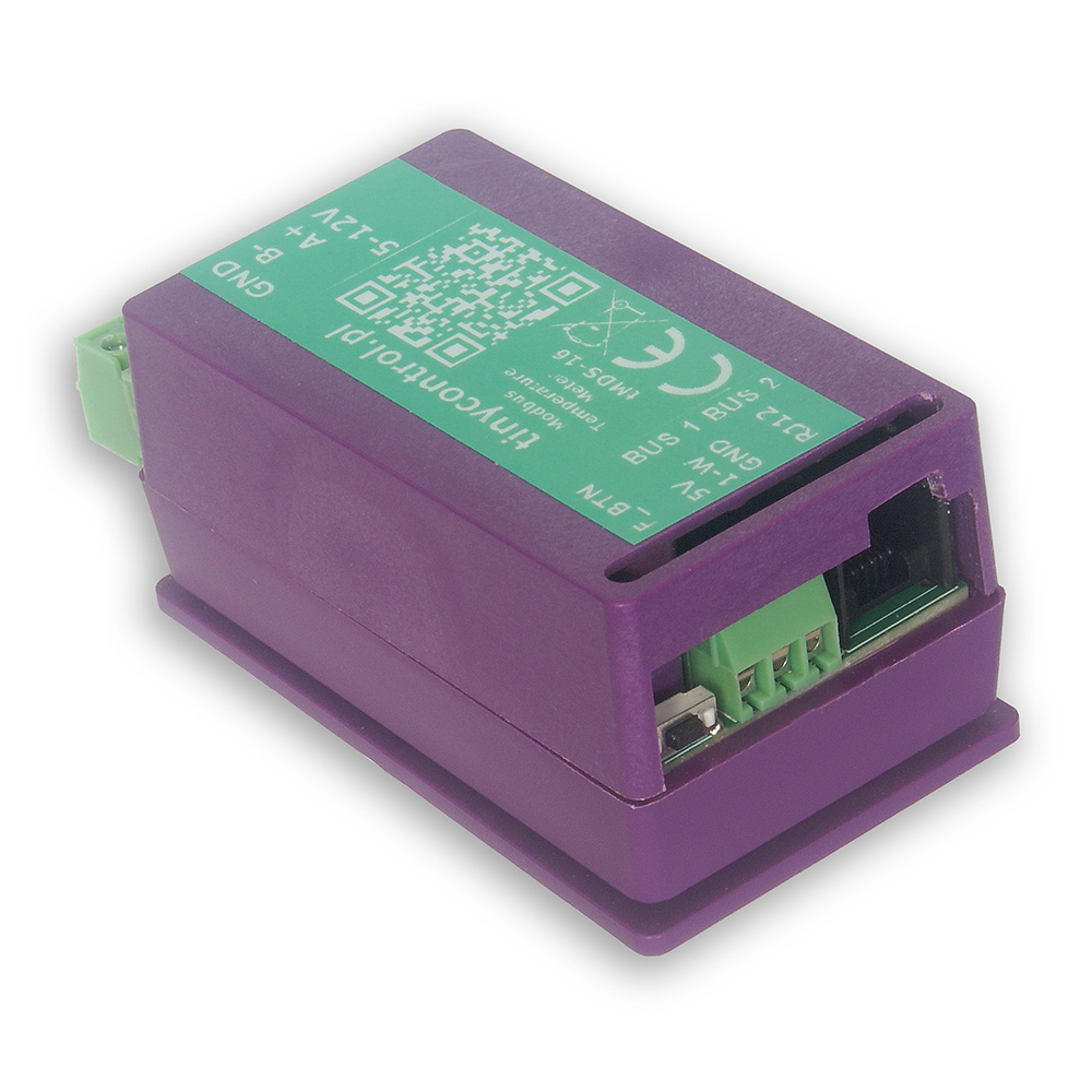
tMDS-16 is a temperature measurement module with Modbus RTU interface. It features two independent 1-Wire buses, each capable of connecting up to 8 DS18B20 temperature sensors, allowing for a total of 16 sensors.
Measurement data is made available via Modbus registers, which include both the current sensor readings and corresponding offset values used for calibration. The calibration ensures accurate and consistent measurements across all connected sensors.
The tMDS-16 is primarily designed to function as an extension module for LK4 or LK3.5+ devices (also compatible with LK3.9), enabling scalable and distributed temperature monitoring.
A ready-to-use configuration file for these devices is available, allowing for quick and hassle-free integration.
By default, the device uses Modbus Slave ID 1, which can be changed via the serial console on the USB.
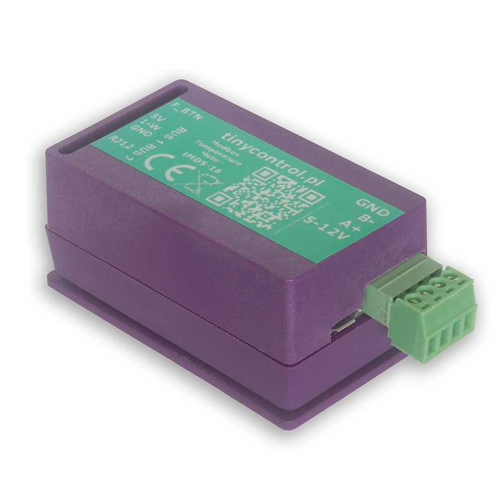
The tMDS-16 integrates seamlessly with LK4 and LK3.5+ devices. It can be powered directly from the LK controller using its 5 V and GND outputs. Then, connect it—either alone or together with other Modbus devices—to the LK’s Modbus A+ and B− terminals to establish communication.
Once connected, configure a custom Modbus module on the LK using the ready-to-use configuration preset available in the Downloads section. You can easily modify this preset to read only the parameters you need, such as selected temperature sensors or calibration offsets.
To update the firmware, the device must be placed into bootloader mode. In this mode, the device appears as a mass storage device named RPI-RP2 when connected to a PC. Simply copy the new firmware file to that storage. After the upload, the device will automatically restart and resume normal operation with the new firmware.
You can enable bootloader mode in one of two ways:
Via USB Console
Connect the device to a PC and open the serial console (see instructions in Advanced Configuration).
Then, send the command bootloader.
The connection will be interrupted, and the device will restart in bootloader mode.
Via JP2 jumper pad (hardware method)
Open the device casing to access the JP2 jumper pad — two adjacent contact fields on the PCB.
Temporarily short the two pads (for example using tweezers or another metal tool) before connecting the device to the PC via USB.
Keep the pads shorted briefly as the device powers on. Once it enters bootloader mode, remove the short.
On older hardware revisions, a FLASH / SW button located on the PCB is used instead.
Press and hold the button before connecting the device to the PC via USB, then release it once the device enters bootloader mode.
Firmware files are available in the Downloads section.
The function button on the tMDS-16 provides a convenient way to perform basic setup actions without connecting the device to a computer.
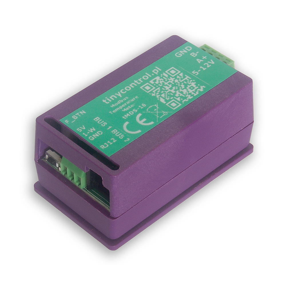
The button is placed near the edge of the board opposite the side with the USB port and the Modbus and power supply connectors.
A status LED next to the button indicates which function will be executed, depending on how long the button is held.
When holding the button, the status LED will blink to signal the selected action:
Press Duration
LED Feedback
Action Triggered
< 2 seconds
1 short blink shortly after press
update_sensors – detect and assign connected sensors
2 - 5 seconds
2 blinks after 2 seconds
set_offsets – auto-calibrate all sensors (offsets saved automatically)
5 - 10 seconds
3 blinks after 5 seconds
reset_sensors – clear all sensor assignments and offsets
> 10 seconds
No action
cancelled (button held too long)
To execute a function, release the button immediately after the desired blink pattern appears.
If the button is held for too long (>10 seconds), no action will be taken.
ℹ️ For more advanced configuration and diagnostics, use the USB console as described in the next section.
To modify the settings, you will need to connect the tMDS-16 to a computer via USB. The device can be powered through USB, so no additional power connections are necessary.
To establish a connection with the board, you’ll need an application that can handle serial communication. Popular choices include:
PuTTy
TeraTerm
PySerial (Python library), which includes useful tools like pyserial-miniterm (for managing connections) and pyserial-ports (for listing available COM ports).
List Available Ports
Run pyserial-ports to list the available COM ports before connecting the device. The output might look like:
COM1
COM3
COM15
COM16
COM17
Connect the Device
Plug in the tMDS-16 and run the command again. The new COM port (e.g., COM11) will represent the connected device.
Connect to tMDS-16
Use the following connection parameters:
Baud rate: 115200
Byte size: 8 bits
Parity: None
Stop bits: 1
Example command:
pyserial-miniterm COM11 115200
Send Commands
Once connected, you can issue commands to the device. Each command must be followed by the Enter key. A useful command is ? or help, which provides a list of all available commands (described below).
Reboot the device into bootloader mode to update the firmware. When connected to a computer, it will appear as a storage device named RPI-RP2, to which you should copy the firmware file with the extension uf2. Then the device will reboot into normal operation mode.
restart
Restart the device.
verbose=X | v=X
Turn on or off verbose mode, which displays more messages.
help | ?
Display this help message with a list of available commands.
Below is the list of Modbus registers available in the device.
The content corresponds to the output of the read_definitions command and includes register names, addresses, types, and divisors.